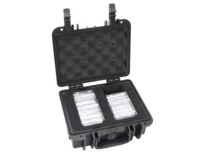
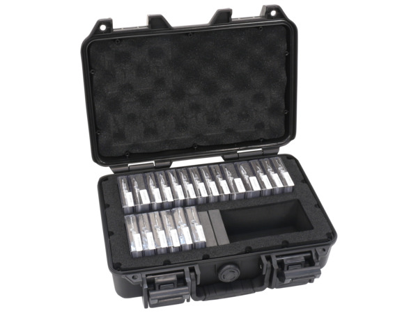
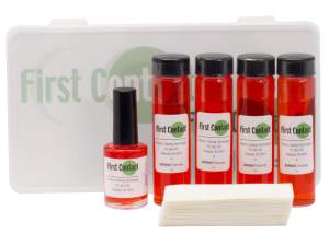
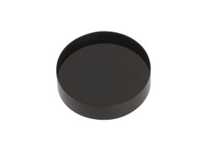
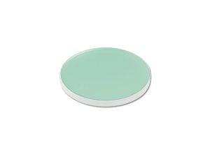
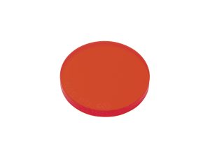
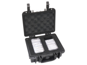
Our long-wave pass filter sets include 13 hard dielectric coated longpass filters that produce a very steep transition between passband and stopband making them far superior to absorptive colored glass filters.
Additional CAD file downloads are not available for this product.
longpass-filter-sets - Drawings
Additional drawings are not available for this product.
Specifications
Type
Longpass Filter Set
Size
Ø25.4 mm
Cut-on Wavelength
400 - 1000 nm
Transmission
≥80%
Effective Index of Refraction
1.7
Surface Quality
80-50 scratch-dig
Temperature Range
-50 to 100°C
Size Tolerance
+0/-0.5 mm
Wavelength Shift with Temperature
0.025 nm/°C
Humidity Resistance
Per MIL-STD-810E, Method 507.3, Procedure III Modified to 7 cycles
Features
Standard Optics Sets with Edge Marked Optics
Our standard optic sets include a wood case organized by part number and key optic information. Confusion in identifying optical components is eliminated with edge marked part numbers on every optic in the OptiSet™. All edge markings are impervious to standard optical cleaning solutions.
-P Optics Sets with Laser Etched Optics
Our -P optic sets include a plastic carrying case with individual protective plastic cases for each optic marked with the part number and key optic information. Confusion in identifying optical components is eliminated with laser etched part numbers on the edge of every optic in the set.
Superior Isolation Between Stopband and Passband
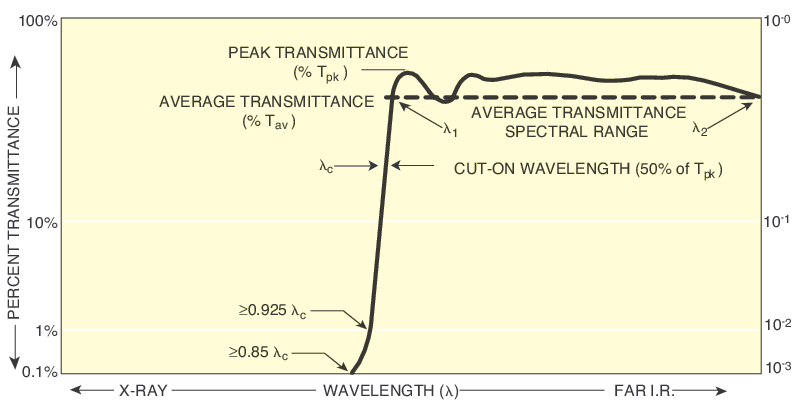
Our long wave pass filters feature both high transmission within the passband, and high rejection within the stop band, as well as a rapid transition, resulting in superior spectral isolation of a desired wavelength range. Out-of-band rejection for our longpass filters is OD≥3 and the stopband spans from X-ray to the edge wavelength. Typical transmission is ≥80% for our long-pass filters.
Angular Sensitivity and Fine Wavelength Tuning
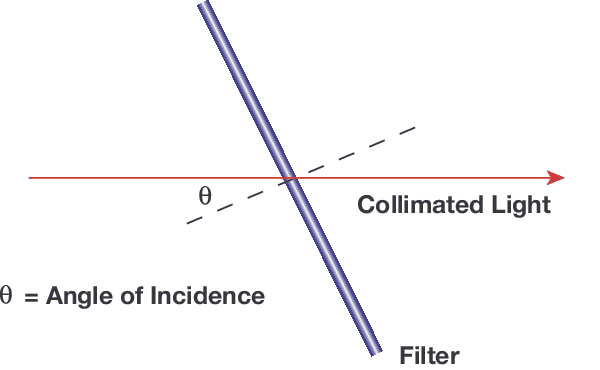
Unlike colored glass filters, the filter edge wavelength for thin film filters will shift to shorter wavelengths with increased AOI. This can be useful for tilt tuning these shortpass filters to your exact wavelength. The shift may be calculated by: λθ = λo [1-(no/ne)2 sin2θ]1/2 where λθ is the wavelength at the new angle of incidence; λo is the center wavelength; no is the index of refraction of the environment (no = 1 in air); ne is the effective index of refraction of the filter; and θ is the angle of incidence. This property can be beneficial as the filters may be intentionally tilted to either stop or allow transmission of light from lasers or light sources near the edge wavelength. Our visible and IR filters have a particularly high ne, allowing more precise wavelength tuning.
In order to provide better service and products, please provide the following brief information.
Password Reset
Enter your email address below to reset your account password.
Password Reset
Email Verification Required
Cart Items Updated
Remove Product
Remove this product from your comparison list?
Check Order Status
Provide an order number and postal code to check the status of an order or download an invoice for an order that has shipped. Login to view your complete order history.
Sign In Required
To access this and other valuable technical resources, please sign in or register for a new online account.