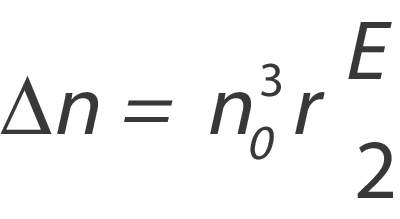
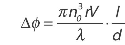
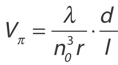
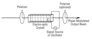
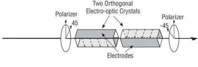
There are several practical limits on the performance of these devices. Mainly, the optical power handling capability of LiNbO3 is limited by an effect known as photorefractive damage. Although this effect is sometimes useful (as in holographic data storage) and does not permanently damage the crystals, it can degrade the performance of a modulator. A modulator with a photorefractively damaged crystal will distort an optical beam passing through it.7 The best way to avoid photorefractive damage is to keep the optical intensity below the specified limit for the modulator. Since the photorefractive effect is highly wavelength dependent, modulators can handle correspondingly higher powers at longer wavelengths. New Focus also uses LiNbO3 that has been doped with magnesium-oxide (MgO). This new material exhibits far superior power-handling capability.
Another limitation results from the fact that all materials with nonzero electro-optic coefficients are also piezoelectric. This means that the same electrical signal that produces phase modulation also generates vibrations. Strains induced by these vibrations alter the indices of refraction via the elasto-optic effect. These vibrations can cause unwanted amplitude modulation or beam displacements at the modulation frequency. The piezoelectric constants of LiNbO3 are fairly weak, and typically do not affect the performance of the crystals as long as the mechanical resonance frequencies (typically between 1 and 10 MHz) are avoided. New Focus will not ship single-frequency modulators tuned near a piezoelectric resonance.
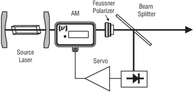
A third limitation when using a phase modulator is residual amplitude modulation. An ideal phase modulator should not modulate the intensity of an optical beam. Amplitude modulation will be induced by sources of back-reflection placed after the phase modulator. Back-reflections result in weak étalons which will alter the harmonic content of the modulated optical beam by introducing a measurable amplitude modulation component onto the beam. Unwanted amplitude modulation can be minimized by properly aligning the input polarization state to the principal axis of the modulator, which is vertical in the case of New Focus™ modulators. You can further reduce residual amplitude modulation by using a collimated optical beam positioned down the center of the modulator. To enable quick and easy alignment of its modulators, New Focus offers the Model 9071 tilt aligner.
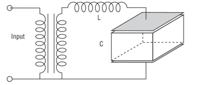
New Focus offers modulators designed to modulate either the amplitude or phase of linearly polarized light over a wide bandwidth, from DC to roughly 100 MHz, with a relatively low drive voltage. The electrical input impedance of these devices in this frequency range is dominated by the capacitance of the electro-optic crystal. This capacitance ranges from 10 pF for the Model 4104 amplitude modulator to 30 pF for the Models 4002 and 4004 phase modulators. Signal generators and frequency synthesizers typically have 50-Ω output impedances, and are not optimized for driving capacitive loads. However, since 30 pF is a fairly small capacitance, most signal generators are adequate drivers at low frequencies (<10 MHz) and small signal levels. High-voltage amplifiers optimized to drive capacitive loads can also be used to effectively drive modulators.
At high frequencies, the impedance mismatch between the cable carrying the modulation signal and the modulator causes a fraction of the RF signal to be reflected back toward the source.8 A directional coupler inserted between the source and the modulator, as shown in Figure 4, can be used to redirect the reflected power to a matched terminator and thereby protect the signal source. Terminating the line driving the modulator with a 50-W load in parallel with the modulator input is an easy way to improve the system's impedance match. At drive frequencies greater than 100 MHz for phase modulators and 200 MHz for amplitude modulators, the RC pole created by this termination will reduce the response to the drive signal by 20 dB per decade. Since the modulators dissipate a minimal amount of power, it is important that all terminators chosen are rated to handle the maximum power output of the signal source or power amplifier. For example, to sinusoidally modulate the phase of an optical beam with a peak phase excursion, m, of 0.5 radian in a 50-Ω system requires an electrical power with a Model 4002 phase modulator. This high power requires the use of power amplifiers and special terminators.