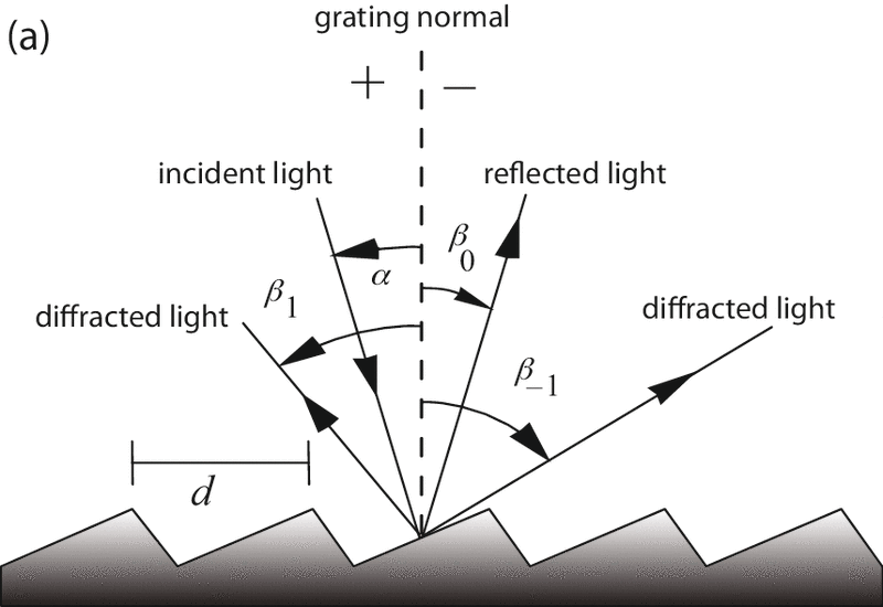
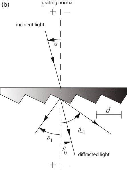
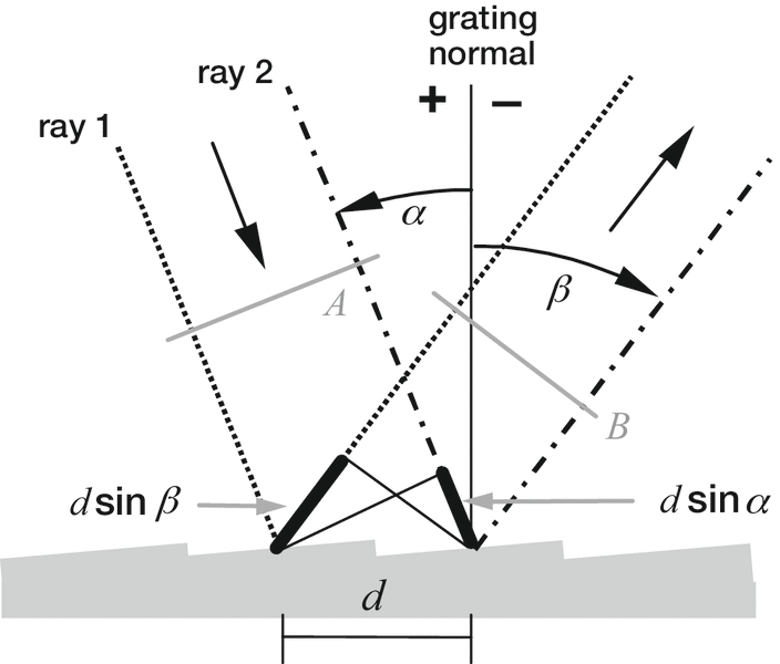
These relationships are expressed by the grating equation
mλ= d (sinα + sinβ) (2-1)
which governs the angular locations of the principal intensity maxima when light of wavelength λ is diffracted from a grating of groove spacing d. Here m is the diffraction order (or spectral order),which is an integer. For a particular wavelength λ, all values of m for which |mλ/d| < 2 correspond to propagating (rather than evanescent) diffraction orders. The special case m = 0 leads to the law of reflection β = –α.
It is sometimes convenient to write the grating equation as
Gmλ= sinα + sinβ (2-2)
where G = 1/d is the groove frequency or groove density, more commonly called "grooves per millimeter".
Eq. (2-1) and its equivalent Eq. (2-2) are the common forms of the grating equation, but their validity is restricted to cases in which the incident and diffracted rays lie in a plane which is perpendicular to the grooves (at the center of the grating). Most grating systems fall within this category, which is called classical (or in-plane) diffraction. If the incident light beam is not perpendicular to the grooves, though, the grating equation must be modified:
Gmλ= cosε (sinα + sinβ) (2-3)
Here ε is the angle between the incident light path and the plane perpendicular to the grooves at the grating center (the plane of the page in Figure 2-2). If the incident light lies in this plane, ε = 0 and Eq. (2-3) reduces to the more familiar Eq. (2-2). In geometries for which ε ≠ 0, the diffracted spectra lie on a cone rather than in a plane, so such cases are termed conical diffraction.
For a grating of groove spacing d, there is a purely mathematical relationship between the wavelength and the angles of incidence and diffraction. In a given spectral order m, the different wavelengths of polychromatic wavefronts incident at angle α are separated in angle:
β(λ) = sin-1(mλ/d - sinα) (2-4)
When m = 0, the grating acts as a mirror, and the wavelengths are not separated (β = –α for all λ); this is called specular reflection or simply the zero order.
A special but common case is that in which the light is diffracted back toward the direction from which it came (i.e., α = β ); this is called the Littrow configuration, for which the grating equation becomes
mλ= 2d sinα, in Littrow (2-5)
In many applications a constant-deviation monochromator mount is used, in which the wavelength is changed by rotating the grating about the axis coincident with its central ruling, with the directions of incident and diffracted light remaining unchanged. The deviation angle 2K between the incidence and diffraction directions (also called the angular deviation) is
2K = α – β = constant (2-6)
while the scan angle Φ, which varies with λ and is measured from the grating normal to the bisector of the beams, is
2Φ = α + β (2-7)
Note that Φ changes with λ (as do α and β). In this case, the grating equation can be expressed in terms of Φ and the half deviation angle K as
mλ = 2d cosK sinΦ (2-8)
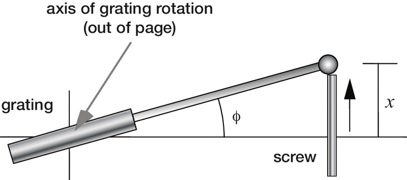
Here K is called the half deviation angle because the angle between the incident and diffracted beams is 2K. This version of the grating equation is useful for monochromator mounts (see Chapter 7). Eq. (2-8) shows that the wavelength diffracted by a grating in a monochromator mount is directly proportional to the sine of the scan angle Φ through which the grating rotates, which is the basis for monochromator drives in which a sine bar rotates the grating to scan wavelengths (see Figure 2-3).