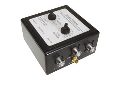
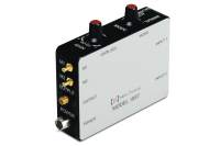
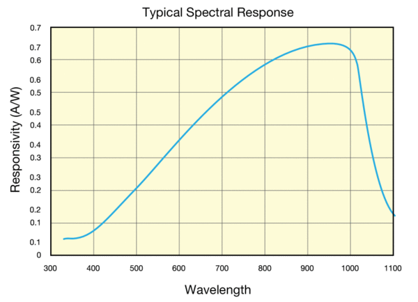
The 2007 Nirvana Auto-Balanced Optical Receiver can cut the effects of laser noise by 50 dB, making even very small signals easy to see. The 2007 has a 400 to 1070 nm wavelength range. In spectroscopy, ellipsometry, or heterodyne-detection experiments, these receivers can yield shot-noise-limited performance without the need for lock-in amplifiers or high-frequency modulation. 8-32 mounting thread. M4 metric adaptor and tool now included.
An external power supply, which must be purchased separately, is required – we recommend our 0901
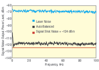
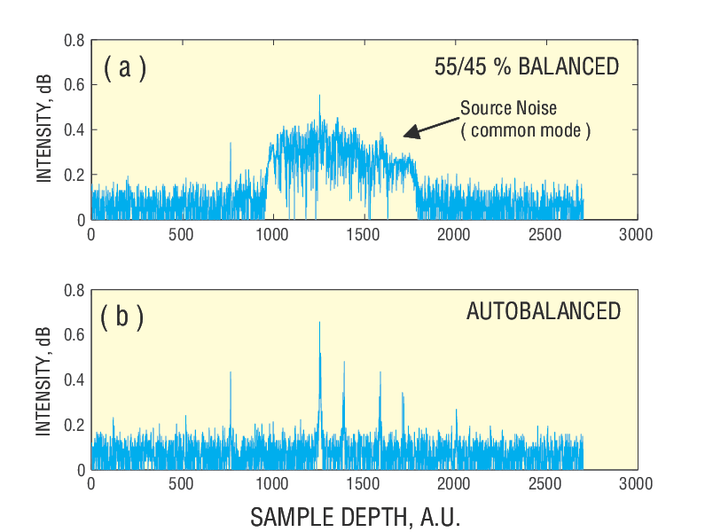
The Nirvana’s patented circuitry subtracts the reference and signal photocurrents, canceling noise signals that are common to both channels. This allow you to measure signal power with 50 dB less noise for the 125 kHz model and 25 dB less noise for the 1 GHz model than in a single-beam experiment.
Maintains Automatic DC Balance Between Reference and Signal Arms
Unlike conventional balanced receivers, the Nirvana’s electronic gain compensation automatically results in balanced detection, even if the average optical intensities on the two detectors are different and time-varying. The auto-balancing technology allows elimination of background noise from dynamically changing systems, including thermal drifting and wavelength dependence, enabling you to achieve the perfect power balance between reference and signal beams.
400-1070 nm or 800-1700 nm Versions
Two Nirvana photoreceivers are offered covering the 400-1070 nm or 800-1700 nm spectral ranges.
Auto-Balanced or Manual Balanced Modes
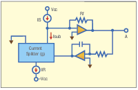
The feedback loop in the Nirvana™ photoreceiver splits the reference photodetector current, IR, to generate the cancellation photocurrent, Isub. When the DC value of Isub equals the signal current, IS, the laser-amplitude noise is cancelled.
Nirvana photoreceivers operate in signal mode, balanced mode, or auto-balanced mode. The output of the photodetector (A) can be expressed as A=(IS – g x IR) x Rf. Here, IS the signal photodiode current, IR is the reference photodiode current, Rf is the value of the feedback resistor, and g is the current-splitting ratio, which describes how much of the reference current comes from the subtraction node (Isub) and how much comes from ground. In signal mode, g is zero and no reference photocurrent comes from the subtraction node. Here, the output A is simply an amplified version of the signal current. In balanced mode, g is equal to 1, and all the reference photocurrent comes from the subtraction node. In this mode, A=(IS–IR)•Rf, the photodetector behaves as an ordinary balanced photoreceiver, where laser noise is cancelled if the DC photocurrents are equal. In auto-balanced mode, g is electronically controlled by a low-frequency feedback loop to maintain equal DC photocurrents cancelling laser noise regardless of the photocurrent.
Additional CAD file downloads are not available for this product.
2007 - Drawings
Additional drawings are not available for this product.
2007
Sign In
Request Resource
In order to provide better service and products, please provide the following brief information.
Password Reset
Enter your email address below to reset your account password.
Password Reset
Email Verification Required
Cart Items Updated
Remove Product
Remove this product from your comparison list?
Check Order Status
Provide an order number and postal code to check the status of an order or download an invoice for an order that has shipped. Login to view your complete order history.
Sign In Required
To access this and other valuable technical resources, please sign in or register for a new online account.